Activity Diagrams - The Parts
Action States and Activity States
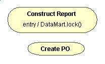
Action and activitiy states are represented by an oval. Inside that shape
you may write any expression that describes an action such as the following:
-
Send a Message to an Object (or service)
-
Create or Destroy and Object
-
Evaluate an expression
-
Encapsulate another set of activities.
Action states can't be decomposed. Action states are also
atomic, meaning that the action is not interruptable. Action states should
also take an insignificant amount of time.
Figure 1 - Example Action States
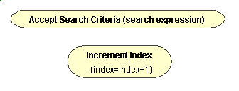
Activity states, by contrast, are non-atomic and can be
further decomposed. It is assumed also that activity states will take some
amount of time to complete. Typically, you can treat activity states as
a composite of other activity states and action states. Expand the details
of an activity state and you'll be looking at, essentially, another activity
diagram.
Figure 2 - Example Activity states
There is no notational distinction between activity states and action
states.
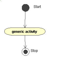
There are two specially notated Action states - start and stop. Start
is notated by a solid circle, stop is notated by a solid circle with a
single ring as illustrated in Figure 3.
Figure 3 - Start and Stop action states.
Relationships
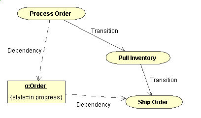
There are only two relationships in Activity diagrams -- Transitions and
Dependencies.
A Transition occurs when the action or activity completes control passes
immediately to the next activity(s) or action(s). In UML this is notated
by a solid direced line, as in Figure 4.
A dependency is used to show relationships between activities (or actions)
and objects, and denotes the participation of an object for a particular
step in the flow of control. Dependencies are notated by a dotted directed
line as shown in Figure 4.
Figure 4 - Relationship Examples
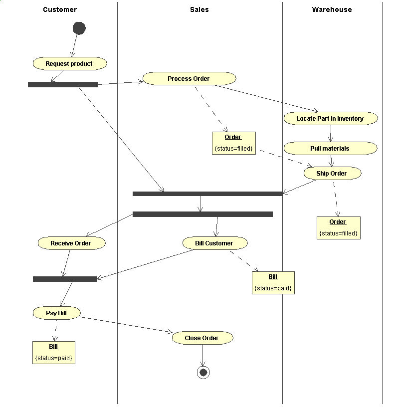
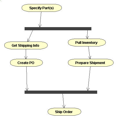
Synch Bars
Synchronization Bars are used to depict concurrent flows, specifically
to depict forking and joining. A synchronization bar is notated by a thick
horizontal or vertical line. Consider the following example for processing
an order.
Figure 5 - Synch Bar example
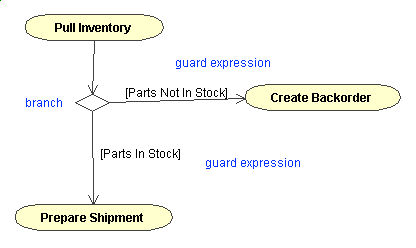
Branches
Anyone familliar to flowcharting will recall "decision diamonds". These
are typically some decision point where some state or expression is evaluated.
In UML these are called branches. A branch has one incoming transition
and two or more outgoing transition. Each outgoing transition should contain
a boolean expression. Additionally, across all the outgoing transitions
the guard conditions should not overlap, otherwise flow control will be
ambiguous. However, the outgoing transitions should cover all possibilities,
otherwise flow would freeze.
Figure 6 - Example Branch
Swimlanes
Especially when modelling workflows, it is useful to denote which actors
perform which activities. You acomplish this you can partition segments
of the diagram into swimlanes. A swimlane specifies a locus of activities
and has a unique name within the diagram. A semantically, swimlane has
no deep ramifications, except to group activities to some real-world entity
performing them. In UML each activity belongs to exactly one swimlane,
however transitions can cross lanes.
Figure 7 - Swimlane Example